
|
|
|
||||||||
| Building your own Cockpit, Wheel etc... Show off your homegrown hardware, or get some help from the experts in wheel building & modification. |

|

|
|
|
Thread Tools | Rate Thread | Display Modes |
 10-04-2008, 16:24 10-04-2008, 16:24
|
#1 |
|
Registered
Join Date: Nov 2007
Location: London England
Age: 43
|
Build along with Hedgehog (r-pod plans inside)
**** Please read through the whole thread before starting to give you a good idea of how everything fits together ****
Hi, I've had a few requests for the plans for my racing pod. I didn't make any to start with so I've decided to put some together. Hopefully anyone who is interested and who ends up building one will post their progress as well and also any suggestions for improvements along the way. I'm going to release the plans in several stages as creating these may take some time. So if you want to build one of these .... 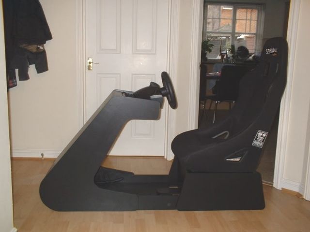 ... I'll do my best to show you how. Any questions or suggestions, just ask. Part 1 - Base unit. It's important that the base is very sturdy so I've constructed this out of 18mm MDF. I am suggesting a improvement to my original design in these plans. The front section of the base doesn't really require the complexity of the 'tongue and groove' system I used. This I think will be a much neater and simpler option.  This picture may clarify the plans further.  If the plans are confusing in any way, please let me know. Suggestions: 1. Consider the seat you are going to use and whether the dimensions are suitable. 2. Are you going to attach a Buttkicker? You may want to think about how to mount it. I cut out a hole in the base and ended up attaching a small table leg to directly to the bottom of the seat. The following image shows the leg which I originally attached to the base. The effect wasn't enough, so I attached it directly to the seat. I then blew my amp so am now going to buy a mini LFE, but that's another story. 3. I'm 6' 2" tall. You may want to consider how you might adjust your seating position if you are going to use a bucket seat. I used wooden blocks between the base unit and the bottom of the seat. This allowed me to adjust the height and recline of the seat. It's now infinitely more comfortable than my real car.  Last edited by SpaceHedgehog; 13-04-2008 at 19:05. |
 |

|
|
10-04-2008, 16:37
|
#2 |
|
Registered
Join Date: Mar 2008
Location: Near Manchester,UK
Age: 27
|
Absolutely brilliant....i just finished my MDF monstrosity. I might actually rip it to bits to build my own version of this one. I might make the seat sit a little lower, and also mount my pedals upside down
 But excellent work, keep them plans coming and i think you`ll be crowned MDF DIY cockpit god 
__________________
If your gonna crash........make it a damn good one!!! #147 on V8Thunder |
| |
|
|
10-04-2008, 16:56
|
#3 |
|
Registered
Join Date: Nov 2007
Location: London England
Age: 43
|
Hi Festa_PWR, I'll probably mount my pedals upside down as well. The shape of the pod actually lends itself better this way than for leaving the pedals on the floor.
I've already investigated this option and have some rough plans but I'm all built-out at the moment but will probably do this in the Summer. |
| |
|
|
10-04-2008, 18:39
|
#4 |
|
Registered
Join Date: Apr 2008
|
My friend could you explain in this picture http://i218.photobucket.com/albums/c...g/basecoat.jpg
the front the rear and the side panel? In your plans in the side view why the one pice is shorter than the other ? How did you put the chair to the base? Where did you find the base for the Buttkicker? Your work is very very good!!! Last edited by Carpe_Diem_Rj; 10-04-2008 at 19:03. |
| |
|
|
10-04-2008, 19:44
|
#5 |
|
Registered
Join Date: Nov 2007
Location: London England
Age: 43
|
Hi, hopefully the enclosed picture will help.
 The bucket seat I have came with 4 bolts to mount it. I bought some longer versions of these bolts (roofing bolts). I simply drilled holes in the top panel of the base and mounted the seat using these bolts. The bolts look very similar to the one below:  The next picture shows the approximate location of the bolts and also the wood block used to raise and tilt the seat. There is a thicker one on the front to increase the incline of the seat. The heads of the seat bolts are large so the holes that you drill for them can be quite large as well. I would recommend drilling and cutting everything on the top panel first as things can be quite tight. I wanted mine to be as small as possible.  The 15cm table leg was bought from a hardware store (B&Q in England). You can probably find something suitable if you have a look around. With the Buttkicker Mini-LFE, you can attach it directly to the bottom of the seat without the need to use anything else. You would only need something like this for the Buttkicker Gamer unit. Last edited by SpaceHedgehog; 10-04-2008 at 19:48. |
| |
|
|
11-04-2008, 23:21
|
#6 |
|
Registered
Join Date: Apr 2008
|
Hi my friend SpaceHedgehog if you can upload more of your plans.
Thnx!!!! for your help! |
| |
|
|
12-04-2008, 14:38
|
#7 |
|
Registered
Join Date: Nov 2007
Location: London England
Age: 43
|
Deleted: Double post
Last edited by SpaceHedgehog; 12-04-2008 at 14:47. |
| |
|
|
12-04-2008, 14:42
|
#8 |
|
Registered
Join Date: Nov 2007
Location: London England
Age: 43
|
Here's a plan for part of the nose section. I had intended to get further than this but making the plan provrd more time consuming than I thought. Apologies for the quality of the scan; if anyone fancies reproducing these in an art/CAD package, please feel free to do so.
Side plan of the nose section:  You may want to create a template first:  Here's a picture of the cut panel leaning against the footwell.  Considerations / Suggestions: 1. Make and assemble the seat base fist. This will determine whether the dimensions of this section are right for you. Several people of varying shapes and sizes have used my pod and these dimensions seem to be ok for them although things may be different for you. 2. I would suggest waiting until you have completed the foot well before starting on this section. It will give you a better idea of the fit as your feet and the pedals will be raised off the ground. 3. Use a 10" dinner plate to get the curve at the front of the pod. You can use cups and other kitchen items to get the curves right between the other angles. |
| |
|
|
12-04-2008, 18:44
|
#9 |
|
Registered
Join Date: Apr 2008
|
You just made my day!
After seeing your original photos I went ahead and emulated the design in Google's Sketchup CAD program. I'm going to start construction this weekend. For the base, I'm surprised that the top panel is fitted between the side panels, rather than on top of them. I agree it looks better this way, but I would have thought the base would be stronger (more load bearing capacity) the other way. How long are the wood screws used to hold the top panel in place? Since I've never worked with MDF before, I have a few questions. Did you end up cutting everything with a circular saw & jigsaw? How many coats each of primer and polyurethane paint did you require? Last edited by Thegide; 12-04-2008 at 18:54. |
| |
|
|
12-04-2008, 19:10
|
#10 |
|
Registered
Join Date: Nov 2007
Location: London England
Age: 43
|
Hi there, glad to be giving something back to this community! I did indeed use a circular saw and a jigsaw for cutting the MDF. Painting the pod requires some time. It's best to use an MDF primer and let this soak well into the sides of the MDF. You may need to use 3 coats of this and sand back after each coat until it's nice and smooth. On top of this I used a flat blackboard paint applying with a small roller. A couple of coats of this is all that's required. I then applied 3 coats of water based matt polyurethane varnish (actually dries a nice satin) and waited for it to cure for a week before using it. It's also advisable to spend a bit of time filling in the holes properly if you intend to screw through the MDF as this can ruin a nice flat surface if it's not done correctly (not that mine is perfect by any means).
I think I used 35mm screws for all the panels on the base, essentially the longest ones that can be used without poking through. All screws have been countersunk'ed into the MDF by a few mm so that the finish would be flat after filling and sanding. The base itself is extremely sturdy. Here's a few pictures to give you an idea of the finish after each stage:    Last edited by SpaceHedgehog; 12-04-2008 at 19:57. |
| |
|
|
13-04-2008, 01:46
|
#11 |
|
Registered
Join Date: Oct 2005
Location: Hamburg, NY (USA)
|
Nice Work! Thanks for sharing
|
| |
|
|
13-04-2008, 04:50
|
#12 |
|
Registered
Join Date: Apr 2008
|
A trip to Home Depot and I'm ready to get started, except it's raining and therefore I can't start my cutting. So instead, if you don't mind, I'll post updates to my progress and hopefully contribute some useful tidbits of info and things I learn along the way about this design.
UPDATED: I bought for the job (so far): - 1 Yonaka Ronin racing seat (reclinable /w sliders) - $200 - 1 quart each of primer, blackboard paint, & water-based clear polyurethane varnish, and a high quality fine hair brush = $80 - foam paint rollers $5 - 1 49"x97"x5/8" MDF = $25 - jigsaw and fine-toothed blades = $50 - 8x1-1/4" and wood glue = $10 - 5/8"x1 1/2" bolts /w 1/4" washers & 5/8" nuts (for bolting the seat) $2 - 2 6'x1x2 high-quality framing wood $8 I went with wood screws over particle board screws, since the thread is finer and less likely to split the MDF. I've tried as best I can to convert from metric to standard for materials, since everything in North America is sold as such. For the base, I'm lowering the height to 8" (20mm) to give it more of a sporty feel. 25mm for me with my seat feels like I sitting in a minivan, not a Lotus. Also the size of my seat base requires a wider base, so I'm going 18.5"x16" for the top panel (47x40mm approx) EDIT: I exchanged a bunch of stuff, and bought a single large sheet of MDF, which was enough for the whole job, excluding the floor board and pedal ramp. I have some scrap flakeboard panels which I will cut for the floor of the footwell and ramp later. The 1x2 framing wood is actually 1 1/2"x3/4". I cut these pieces in half to make 3/4" square pieces which I will use to reinforce joints, since I could not find 1" square (25mm x 25mm wood). Last edited by Thegide; 18-04-2008 at 17:07. |
| |
|
|
13-04-2008, 09:44
|
#13 |
|
Registered
Join Date: Nov 2007
Location: London England
Age: 43
|
Hi Thegide, it's great that you're getting motivated to build. That's often the last hurdle to actually getting what you want so good for you! If there's anyone else out there having trouble with getting motivated to do something, close your eyes and really try to picture youself with the job completed (works well for me anyway).
It's good that you're thinking about the dimensions and it would definitely be a useful addition to this thread if you could post details of yours which will be using a slider/frame. The only thing that prevented me from doing this was the cost of it but it would be a really good enhancement to the pod. The only observations I have in this area is that the slider will raise the height of the seat so lowering the base would seem sensible but also the footwell is raised off the ground by a few cm's, I used 25mm wood strip to raise the bottom of the footwell off the floor (the MDF doesent lay flat on the floor directly). My MDF base is also 12mm thick** so this raises the platform that my feet will be rest by approximately 37mm. Given that pedal bases can also raise your feet further, you can see that you can end up raising your feet by a reasonable amount. One other thing to think about is the effect that adjusting the height of the seat will have on the dimensions of the nose section. Lowering it means that your legs may stretch out further. If you have long legs like I do, you may want to think about lowering the total height of the nose section and also extending it slightly. As previously mentioned, the dimensions that I am using accommodate lots of different sizes of people. If anyone was any larger than I am, the position of the pedals might be restrictive with g25 pedals laying flat on the floor - the base is quite long and the dmensions between the front of the pedal base and the front of the pedals is quite large and can waste a lot of available space. I'm intendling to mount these upside down at some point in the future and should be able to do this quite easily with the current design. For finishing the paintwork, I would definitely recommend using a small foam roller used for painting radiators. I used a brush for applying the MDS primer though. **For the sake of portability, I used 12mm MDF for the nose section and the footwell. I would recommend that you use 18mm if you are not intending to move it much. Last edited by SpaceHedgehog; 13-04-2008 at 09:52. |
| |
|
|
13-04-2008, 12:01
|
#14 |
|
Registered
Join Date: Nov 2007
Location: London England
Age: 43
|
Ok, time for the third installment. This part will concentrate on building the footwell. As mentioned in the previous post, I used 12mm MDF so it was lighter and more transportable. The whole section is pretty stable but I would recommend using 18mm MDF if you are not going to move it around; no point in using a thiner material unnecessarily. The seemingly odd cut at the side allows for doubling up on the thickness which further improves the sturdiness on the design. When the nose section is assembled, you will see how we can improve things still further by overlapping the two sections.
Footwell plans:  *** Correction to above, Front Board should be the same width as the foot board i.e. 38cm or 36.5cm - sorry! Once complete, it should look similar to this:  To give you an idea of how it looks from the inside with everything assembled:  Considerations: Don't glue everything together just yet, the sides of the panels will need to be cut further. This will be done after the nose section has been completed. Raising the foot board off the ground using the wood strip provides a better area to screw the sides onto. I would be inclined to not attach the front panel of the seat base just yet. This section will need to ensure that the footwell section can slide underneath unobstructed and will need modifying to do so. This diagram may help to explain (ignore the 'tongue in here' bit, it's the 'sides in here' bit we're interested in):  I have used a length of 100cm fo the footwell. You may be able to get away with slightly less than this. The footwell retracts under the base of the seat for adjustability. Here are some pictures to show how this works (please ignore the 'tongue' setup here, the new design used will be much cleaner. If I'm honest, this was to make up for a mistake where I inadvertantly sawed off more than I should have! looks good anyway though).    The overlap on the plans is important if you don't want the footboard base showing with the side panels attached. Last edited by SpaceHedgehog; 13-04-2008 at 17:32. |
| |
|
|
13-04-2008, 17:14
|
#15 |
|
Registered
Join Date: Nov 2007
Location: London England
Age: 43
|
Right, here's the last main entry, I guess anything further will focus on cosmetic and general finishing.
One thing to mention first. It goes without saying that any pair of panels (base sides, nose section and footwell) should be cut at the same time to ensure they match. This section will complete the build of the nose section and only 4 panels are required to do this. Here's the plan:  The panels 1,2,3 and 4 attach in the positions shown in this plan:  The next step will be to overlap the side sections with the footwell. Wood strip will be used to attach the panels to (approx 20mm x 20mm cross section will be fine) the front of the nose cone so remember to allow for this. Draw around the nose section onto the front of the side panels on the footwell section. Basically we want to get from this:  To this:  To give you an idea of how it will look when attached, this a front view:  Ok, I hope you are with me so far. Any questions, please ask. The next step will be to assemble the sides and panels 1 and 3. Once this has been done, the nose can be glued 'n screwed to the front although it may be worthwhile doing a dry run and ensuring you can attach panel 2 before gluing it all together. It's important that the front board of the footwell section is as far forward as it can be without poking outfrom the bottom curve of the nose side panels. This will ensure that you have sufficient leg room in the pod.  Once it's all be attached, it should look something line this from the top:  The next things will be to cut a section of wood beading which will glue to the top and bottom of panel 1 at the front of the nose section. Here's a picture with it in place:  When it's all completed, it should look like this:  Ok, that's it for now, the pod build will be almost complete at this point. I'll follow up with another post soon ..... |
| |
|
|
13-04-2008, 17:36
|
#16 |
|
Registered
Join Date: Apr 2008
|
Excellent instructions, and thanks again so much for uploading them.
I do have a question regarding the slotted panels located at the front base of the nose section. I gather these are for setting the angle of the pedals, but can you elaborate on how this system works? Still contemplating some modifications to the design to reduce overall weight without compromising stability. I was thinking about going 18mm MDF on the nose sides, and trying to avoid having to double up on the MDF. The other places that I might look to modify for reduce weight would be the front & rear panels, and the floor panel. Just out of curiosity... any rough guesses on the weight of your nose section? Last edited by Thegide; 13-04-2008 at 17:43. |
| |
|
|
13-04-2008, 18:05
|
#17 |
|
Registered
Join Date: Nov 2007
Location: London England
Age: 43
|
Glad to help! The slotted sections may be worthwhile making but it depends on how you're going to use your pedals. Essentially it provides an adjustable backboard for any set of pedals to push up against. It's fairly basic in principle but works well.
I'll run you through the process of making them and then you can decide if this will work for you. First I made the slots to attach to the inside of the pod.  Then I made the backboard and the pedal stand. You can see a block of wood sticking out of the back of the inclined stand which fits into the hole in the backboard. The backboard fits into the slots on the inside of the pod.   This is how my XBOX 360 pedals looked one attached to the pedal base:  I don't need to use this currently with the g25 pedals as they're fine on the carpet and don't move at all. Regarding the weight, I'd hate to guess. It's not heavy really, It's just a bit of an awkward shape. I'd say it weighs less than the seat with the base attached. The suggestions youve made about the panels seem pretty sensible to me. There's certainly no need to use 18mm on the floor base. I would recommend doubling up on the sides though even if you do use 12mm MDF for all of the footwell section (sides included). Last edited by SpaceHedgehog; 13-04-2008 at 18:23. |
| |
|
|
13-04-2008, 18:51
|
#18 |
|
Registered
Join Date: Nov 2007
Location: London England
Age: 43
|
A few final tips to get the pod complete. I'm enclosing a few pictures from various angles to clarify a few things. On the plans for the nose section I have suggested removing a section from the lower top panel. This picture shows this in more detail and how I've finished off the 'dashboard'.
 If your wheel has cables which don't attach underneath the base, you may also want to cut a hole for them in the top panel. If you're going to use a g25 only, you could consider removing a smaller piece of the top panel so you can hide the wires completely. The cables can then run between panels 3 and 4. I'll almost certainly do this and make another 'leather-look' top to hide the hole for the cables.  I'll no doubt post further information about the plinth and the shifter stand soon but hopefully this is enough to begin with. Last edited by SpaceHedgehog; 13-04-2008 at 19:06. |
| |
|
|
18-04-2008, 17:20
|
#19 |
|
Registered
Join Date: Apr 2008
|
Just a quick update.
Most of the panels are cut. I did a test assembly on the seat base with the seat mounted and it's very sturdy. The sliders are mounted as forward as possible on the seat base, so that the seat has its full sliding range (otherwise the 1/2 lip on the rear seat panel would prevent this). Even fully slid forward, the base is solid and does not tip. On a side note, having everything cut, I'm surprised at just how small this build is (don't worry - the fit IS right It looks quite a bit larger in the photos.
|
| |
|
|
18-04-2008, 20:05
|
#20 |
|
Registered
Join Date: Nov 2007
Location: London England
Age: 43
|
That's great news and I'm glad the build is proceeding well! It is nice and compact which was one of the main considerations for the original design. Infact it had to be able to hang on the wall of the garage. Not got around to doing this yet, maybe in the summer.
Have you had to adjust the dimensions a lot or is everything fairly similar to the dimensions posted (aside from the increased width and lowering of the base of the you mentioned previously)? It would be great to see some pictures either in this thread or your own. |
| |
|
|
20-04-2008, 10:32
|
#21 |
|
Registered
Join Date: Apr 2008
|
Everything is pretty similar so far. I finished carving out the side panels today, as well as the side panels to the footwell.
It was tricky figuring out how to get straight cuts along the angles for the side panels. In the end, I ended up doing a rough cut several inches from my cut lines with a handheld circular saw, then attached a guide to the excess trim so that the final cuts could be done with the table saw to get perfect precision. This only worked for the outside lines though. The inner lines to the "C" shape I ended up doing with steady hands and a jigsaw; I'm pretty happy with the result, given the lines are almost dead straight. I should be in good shape to assemble the nose cone today. Still have some sanding to do to round out the curves of the side panels. As well, I'm contemplating modifying how the footwell slides into the seat base. Since I'm not going with the "tongue" design, I need to figure out how to lock the seat base to the footwell. I thought of hiding the locking mechanism under the seat base, but this would be difficult to access. I'm leaning towards using tee nuts and bolting it down from the outside. Anyways, I'll try to take some pictures and up them later today. When everything is done, I'll also up my version of the blueprints. Last edited by Thegide; 20-04-2008 at 10:35. |
| |
|
|
20-04-2008, 11:36
|
#22 |
|
Registered
Join Date: Nov 2007
Location: London England
Age: 43
|
Sounds like it's coming on a treat! It doesn't take too long to build if you get down to it.
For the rounded edges on everything, I used coins and egg cups etc and then cut around them with a jigsaw and finished of by sanding. For attaching the base to the footwell, you might consider doing something like the picture below to keep things neat. It's effectively using the same approach that I have but with 2 bolts/ allen keys rather than 1. If you attach some wood (1" x 1" cross section) to the bottom of the front panel of the seat base and drill a couple of holes in it, and then drill some corresponding holes into the base of the footwell you can drop allen keys or bolts through to keep it all in place. You can make a series of these holes on the footwell to allow it to be adjusted back and forth. Here's a very bad photo of the design (my scanner is playing up):  |
| |
|
|
21-04-2008, 02:00
|
#23 |
|
Registered
Join Date: Apr 2008
|
Snapshot of my progress as of Sunday.
seat base:  nose cone and seat base test setup:   closeup of nose cone   seat base with seat attached (note the sliding track for adjustable seat):   Still have to build the footwell. You might notice that I didn't make cutouts in the front panel of the seat base - because I'm still deciding how I want to fix the footwell to the seat base. I bought the tee nuts and some hex bolts. Not quite as pretty as the black cap bolts you've used, but my shop only carried those in metric format... and tee nuts only in standard format. So, hex bolts it is - I went stainless steel; they still look nice. Last edited by Thegide; 21-04-2008 at 02:14. |
| |
|
|
21-04-2008, 09:44
|
#24 |
|
Registered
Join Date: Nov 2007
Location: London England
Age: 43
|
Fantastic!!! You've probably done most of the hard work now, the footwell is quite easy to make. Does the size fit ok?
Keep posting pics, I'm sure you will inspire others to start building as well. Any idea on how or if you're going to finish this off (vinyl etc - I'm still thinking about a couple of designs here)? Are you thinking of adding any extra bits? Let me know if you want me to post details of the shifter stand I made and I will do so. Jealous of the fully adjustable seat  The finish looks great as well. The finish looks great as well.
|
| |
|
|
21-04-2008, 15:32
|
#25 |
|
Registered
Join Date: Apr 2008
|
Thanks. The size fits great. I took a premature test drive last night in GT5:P and it was amazing. I should be able to finish the cuts for the footwell floor and the pedal ramp in the next day or two. Assembling the nose cone was by far the trickiest part. I'm glad it's done!
I was thinking about adding some finishing touches with 1/4" round moulding as you have done. Then it's covering up the screwheads and painting the whole thing. I'll probably look to find some commercial carpet or rubber mat to line the footwell with as well. If the tee nut system works well for affixing the base, I might also apply that to the nosecose and make it 3-piece modular for easier moving/storage. I'll scan the plans and upload them later today. |
| |
|
|
|
| Thread Tools | |
| Display Modes | Rate This Thread |
|
|


 Linear Mode


